Rockflex_PUR 0,6-1kV
Download Datasheet PDF Rockflex_PUR 0,6-1kV Cable Type: ROCKFLEX-PUR – 0.6/1kV Halogen Free outer sheath Main Application: Power supply to mobile... read more
Description
Rockflex_PUR 0,6-1kV
Cable Type:
ROCKFLEX-PUR – 0.6/1kV
Halogen Free outer sheath
Main Application:
Power supply to mobile equipment with high risk of mechanical damage in mining and tunneling.
Cable is suitable for application where it is deflected in one plane only. Maximum speed 60 m/min
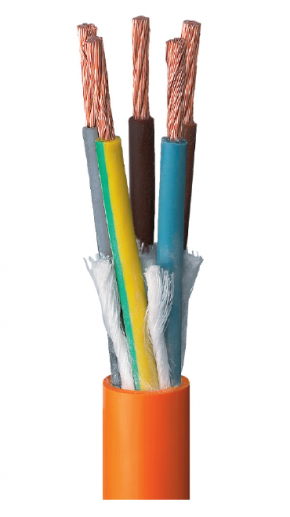
| Construction | |
| Phases Cores | |
| Conductors | Plain copper, flexible class 5 IEC 60228 |
| Insulation | XLPE special compound Brown – Black – Grey |
| Earth Cores | |
| Conductors | Plain copper, flexible class 5 IEC 60228 |
| Insulation | XLPE special compound colour: yellow/green |
| Control cores | |
| Conductors | Tinned copper , flexible class 6 according to IEC 60228 |
| Insulation | Thin thickness made of special technopolymer colour : white – blu |
| Cable construction | Phase cores laid up with earth cores in the interstices . 2 control conductors in over-interstitial areas |
| Binder | Non hygroscopic synthetic tape (if required by manufacturer) |
| Bedding | Special flexible technopolymer compound |
| Outer sheath | Polyurethane special compound abrasion and tear resistant, excellent hydrolysis resistant. YELLOW RAL 1018 colour type |
| Marking | Rockflex PUR 0,6/1 kV 3×70+3G16+2x1x1,5 mm2 month/year CE (+ metric) (marking Inkjet printed) |
| Parameters | |
| Electrical | Rated voltage Uo/U = 0,6/1 kV |
| Maximum permissible operating voltage in AC systems Um = 1,2 kV | |
| AC test voltage over 5 minutes 3,5 kV | |
| Current Carrying Capacity According to DIN VDE 0298 part 4 | |
| Thermal | Fully flexible operation -20° C |
| Fixed installation -30° C | |
| Maximum permissible operating temperature of the conductor 90° C |
|
| Short circuit temperature of the conductor 250° C | |
| Mechanical | Tensile load Up to 20 N/mm2 |
| Minimum bending radii 6 OD | |
| Reeling operation Up to 60 m/min | |
| Chemical | Outer sheath performance Halogen free |
| Finished cable Flame retardant – IEC 60332-1-2 |
Technical Data
| Number of cores and nominal cross section | Main conductors copper | Protective earth cond. copper | Control conductors insulated | Overall diameter | Net weight | Bending radius minimum value | Maximum permissible tensile force | Current carrying capacity at 30°C Spiral or | Short circuit current – 1sec. | |||||
| nom. diam. | nom. diam. | nom. diam. | min. | max. | approx. | fixed | reeling | Static | Dynamic | laid straight | 1 layer | 2 layer | 90 ° to 250 °C | |
| n x mm² | mm | mm | mm | mm | mm | kg/km | mm | mm | N | N | A | A | A | kA |
| 4G16(*) | 5,1 | 5,1 | N.A. | 20,0 | 22,0 | 870 | 132 | 176 | 960 | 1280 | 99 | 79 | 60 | 2,29 |
| 3×25+3G6+2x1x1(*) | 6,5 | 3,0 | 2,3 | 22,5 | 24,0 | 1150 | 144 | 192 | 1125 | 1500 | 131 | 105 | 80 | 3,58 |
| 3×35+3G6+2x1x1.5 | 7,5 | 3,0 | 2,6 | 26,0 | 28,0 | 1550 | 168 | 224 | 1575 | 2100 | 162 | 130 | 99 | 5,01 |
| 3×50+3G10+2x1x1.5 | 9,1 | 3,9 | 2,6 | 29,5 | 32,0 | 2150 | 192 | 256 | 2250 | 3000 | 202 | 162 | 123 | 7,15 |
| 3×70+3G16+2x1x1.5 | 10,8 | 5,1 | 2,6 | 34,0 | 37,0 | 3000 | 222 | 296 | 3150 | 4200 | 250 | 200 | 153 | 10,01 |
| 3×95+3G16+2x1x1.5 | 12,1 | 5,1 | 2,6 | 37,5 | 40,5 | 3650 | 243 | 324 | 4275 | 5700 | 301 | 241 | 184 | 13,59 |
| 3×120+3G25+2x1x1.5 | 14,3 | 6,5 | 2,6 | 42,0 | 45,0 | 4800 | 270 | 360 | 5400 | 7200 | 352 | 282 | 215 | 17,16 |
| 3×150+3G25+2x1x1.5 | 16,1 | 6,5 | 2,6 | 47,5 | 50,5 | 5850 | 303 | 404 | 6750 | 9000 | 404 | 323 | 246 | 21,45 |
| 3×185+3G35+2x1x1.5 | 17,5 | 7,5 | 2,6 | 52,0 | 55,0 | 7150 | 330 | 440 | 8325 | 11100 | 461 | 369 | 281 | 26,46 |
| 3×240+3G50+2x1x1.5 | 19,9 | 9,1 | 2,6 | 58,0 | 61,0 | 9250 | 366 | 488 | 10800 | 14400 | 540 | 432 | 329 | 34,32 |
| Correction factors for ambient temperature other than 30 °C | ||||||
| °C | 20 | 25 | 35 | 40 | 45 | 50 |
| K | 1,1 | 1,05 | 0,95 | 0,89 | 0,84 | 0,77 |